UltraSonic Ride Height Control
The goal of this project is to control the ride height of a foiling moth with an ultrasonic sensor. The ultrasonic sensor is an alternative to the existing mechanical “wand” based system. While not class legal, the development unlocks potential future electronic foiling possibilities and allows the Kroova team to continue to refine their skills. This is a project that involves many interdisciplinary aspects including mechanical design, composite engineering, software programming, electrical design, and control loop engineering. The Kroova team wants to specially thank Jamestown Distributors for sponsoring this project and making it possible.

Special thanks to Jamestown Distributors for the sponsorship!
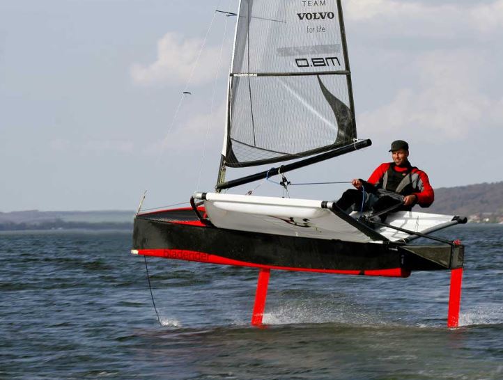
A bladerider foiling moth.
Advantages of Electronic Ride Height control
The advantages of electronic ride height control are significant. Currently, every time the moth moves over small waves the wand skips along, and the flap on the foil moves as well, resulting in lost energy and higher drag. If the ultrasonic sensor was recording the ride height, not only would there be a drag reduction due to the lack of wand , but one could also filter out the chop, and the flap could stay at a more constant setting as it rides through the water. One could then tune the control loop (PID) to respond only to certain changes based on wind conditions, wave height and rider preference. In heavy chop for example the rider may choose to operate at a lower ride higher to increase control.
In the clip below it is possible to see how much the wand skips over the water even in relatively flat water with little chop.
Ball TILT Demo
The project is broken up into four different stages. The first stage is a simple ball tilt demo. This was used to build confidence integrating the electronics system with the ultrasonic sensor, servo, and PID tuning. A short video of the ball tilt demo is below. The goal is to get the ball within a certain distance from the sensor (right side) in as little time as possible.

FOAM WING CAR-TOP PID TUNING
The next stage is the development of a controllable wing that mounts to a track and rides on top of a car. A servo is used to control the angle of attack of the wing, and the ultrasonic sensor is mounted to the track to record ride height. This allows the team to further develop an understanding of the integration of the PID loop, sensor and servo. Additional a number of more complex variables can be introduced into the testing scheme. Testing with each additional variable on the car (as opposed to on the water) allows the team to keep the system controlled to best understand each variable independently. The testing scheme for the Wing on the car includes.
· First flight – record data
· Adding or subtracting weight from the wing (to change the inertia of the system) and test the tuneability of the PID loop
· Adding a bin of water underneath the sensor to simulate the variability in the readings. Water disturbances will occur naturally due to driving.
· Spraying/Splashing water on the system to understand how the data filter will handle random readings
The video to the right shows the system as well as the effect of different PID gains on stability at different speeds.
SYSTEM MOBILITY
In order to be able to test the wing and collect data from the wand and ultrasonic sensor the team needed to make the system mobile. This was achieved by mounting all the necessary components inside a waterproof box. The following components are inside the testing and control box.
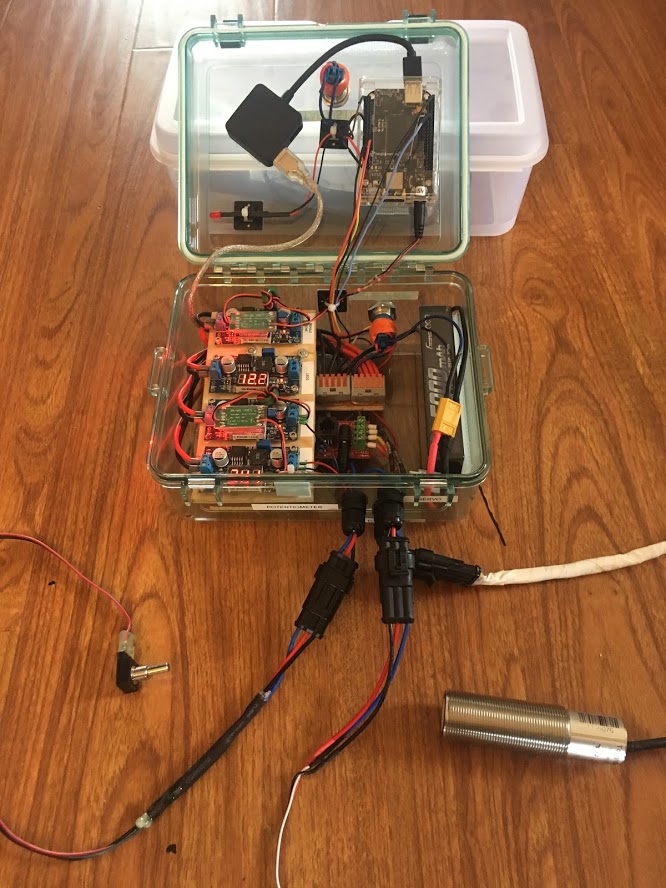
· Battery: 5000 mAh 7.4 V LiPo
· BeagleBone
· USB Hub
· ToughSonic RS232-USB Converter and Power Supply
· Voltage Regulators
· 1-Servo (Runs on 7.4 V)
· 2-Button LEDs (Runs on 12 V)
· 3-ToughSonic (Runs on 24 V)
· 4-Beagle Bone (Runs on 5.5 V)
· 2 x Buttons
· On/Off and Start/Stop
· Gland Connectors for the System
SENSOR PLACEMENT
From a performance standpoint, the further forward (on the boat) the ride height sensor can be, the better. This can be seen in the moth class, as the wand placement has been moving further and further forward. In an ideal world, one would even tilt their sensor and read well out in front of the boat and then tune the control loop to handle the incoming waves. In the future there may be technologies that can handle this. Perhaps we will see systems that use video processing of waves and chop hundred of feet in front of the boat, effectively mapping the ocean surface! The goal of this project however is to try to mimic the performance of the wand as a starting point. The disadvantage of placing the ultrasonic sensor in front of the bow (on a bow sprit for example) is the possibility of boat pitch playing a role in the readings. For this reason the team decided to mount the sensor a few feet back from the bow to closely mimic the readings of the wand.
The first mounting location was too low, and the sensor mount was splashing water into the seen in the video to the upper right.
DATA COLLECTION
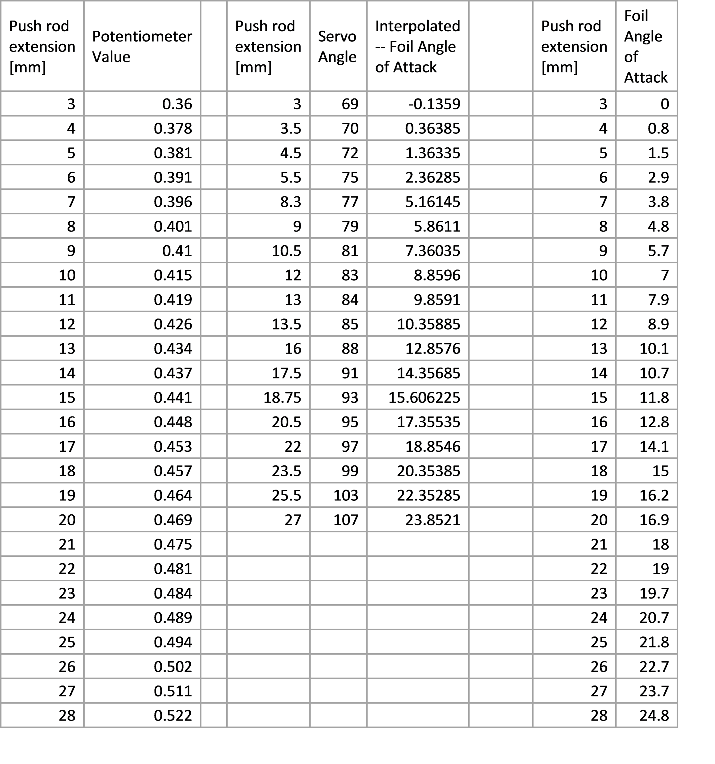
The third stage (which is happening at the same time as the wing test stage) is data recording of the ultrasonic sensors compared to the mechanical “wand”. Rather that tune the system from scratch the first time the team goes sailing, it was decided to mount a rotational potentiometer to the wand along with the mounted ultrasonic sensor. We took video of the flights, and then use the data to preemptively tune the PID loop and get the best results possible.
Some initial test runs can been seen in the video.
Correcting Data Lag Due to Serial Buffer
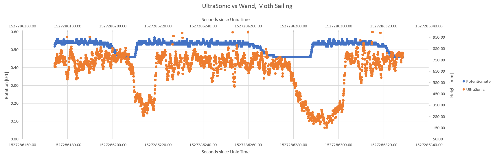
After sailing the moth with the wand potentiometer and ride-height ultrasonic sensor rigged, we took a look at the data we gathered. Pretty quickly we noticed that the ultrasonic data we had collected had a time delay in it, and over longer runs actually seemed to have a time scaling issue as well. The first image shows a plot of the data with a visible offset between the two sensor readings which should be closely synchronized.
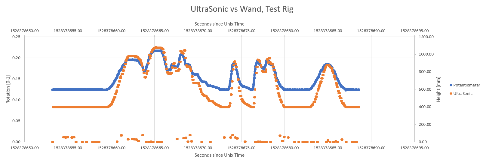
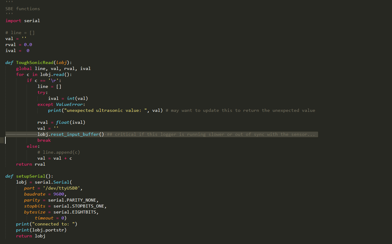
After some discussion we realized there could be an issue with the serial buffer storing incoming data and that data becoming stale and old if the buffer wasn't being cleared properly. We added the necessary code (a single critical line), visible in the second image, and setup a quick test rig to link the motion of a wand and the ultrasonic sensor.
Sure enough, the buffer clearing after each successful read solved the problem! The properly synchronized sensor data can be seen in the last image.
Potentiometer Selection and Drift
We used a potentiometer to measure the rotation of the wand on the moth while sailing. One of our main selection requirements was for the potentiometer to be waterproof. Besides the waterproof requirement we didn't have many requirement concerns and went ahead and chose one of the first readily available potentiometers.
This quick component selection led to a few undesirable characteristics in the system. The first issue was that the potentiometer was a 360° continuous rotation pot, and since we only needed ~60° of rotation measurement we sacrificed a good portion of our resolution.
The second issue was exacerbated by the less than optimal resolution already described. The pot we chose didn't include any quantitative data on its resistance change based on temperature, here's the data sheet for reference. We took land measurements to correlate the potentiometer values to flap movement which were done in the warm San Diego air. The potentiometer was then constantly being dunked in cold ocean water while sailing and varied enough in resistance to overshoot the calibration values we had taken just an hour earlier.
For this project we've been able to accept the drift and resolution issues since they only effect our simulations and not the final flight characteristics. For future projects involving precise rotational measurements we'll certainly consider several improvements based on what we've learned: -- Potentiometers with increased resolution, and or precision -- Potentiometers with listed temperature coefficients -- Transducers that aren't resistance based, such as various encoders -- Potentially wiring the potentiometer in a circuit that is less susceptible to temperature effects, such as the variable voltage divider suggested in this blog post.
Foiling with Remotely Controlled Ride Height

In order to remove the mechanical wand and foil the boat with guidance from the ultrasonic sensor, we have installed a servo that can actuate the flap on the control box.
The next step was to remove the wand and remotely control ride-height to determine how much input the wand was actually providing to the wing flap.
Check out the video to see Max Kramers controlling the ride height of the moth via radio while Dan sails the boat. (Action starts at 1:09)
Foiling with the Ultrasonic Sensor Alone!
The fourth and final stage is to achieve electronically controlled foiling without the help of the wand. With data gathered from the ultrasonic sensor, software allows us to actuate the wing flap and achieve stable foiling. Further tuning is being done to refine the system and to account for things like heel, surface spray, etc., but we are excited to announce that we successfully foiled with the ultrasonic sensor and IMU alone!
See the short video below for some shots of the action.
